TwinCAT 3
In this tutorial, you'll learn how to control ATOM over EtherCAT with TwinCAT 3.
If you'd like to skip this tutorial, download the completed example project: AtomExampleTwinCat.zip.
If you are unfamiliar with TwinCAT 3, check out PLC programming using TwinCAT 3 video series by Jakob Sagatowski.
Prerequisites
- A PC with TwinCAT 3 Engineering installed
- We recommend using
TwinCat XAE Shell: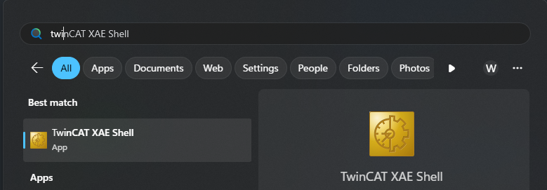
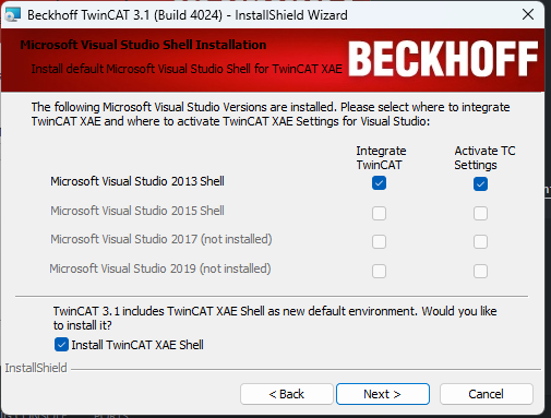
- This can be installed during the installation process:
- An Intel-based network interface:
 TwinCAT 3 requires an Intel-based network adapter to work properly.
- We recommend using
- (Optional) A Beckhoff EtherCAT PLC (e.g., CX9020, CX5130)
- TwinCAT 3 includes a built-in soft PLC simulator that you can follow along with. This tutorial will cover both options - using a PLC and using the soft PLC simulator.
- Download ATOM's ESI file: Atom.xml
Hardware setup
To simplify this tutorial, we skip connecting a load to ATOM. The fieldbus configuration remains the same regardless of whether you connect a load or not.
EtherCAT ID switches
ATOM has two rotary switches that together set the EtherCAT ID. The EtherCAT ID is a two byte ID that unqiuely identifies ATOM on an EtherCAT network.
The X1 rotary switch sets the low byte of the EtherCAT ID, and the X10 rotary switch sets the high byte of the EtherCAT ID.
For example, when X1 is set to 1 and X10 is set to 2, the EtherCAT ID is 0x21 (33 in decimal).
The EtherCAT ID is used for manual addressing of EtherCAT devices which is useful for seamless device replacement and consistent identification across restarts. In this example, we use TwinCAT's built in automatic addressing, so the EtherCAT ID switch positions don't matter.
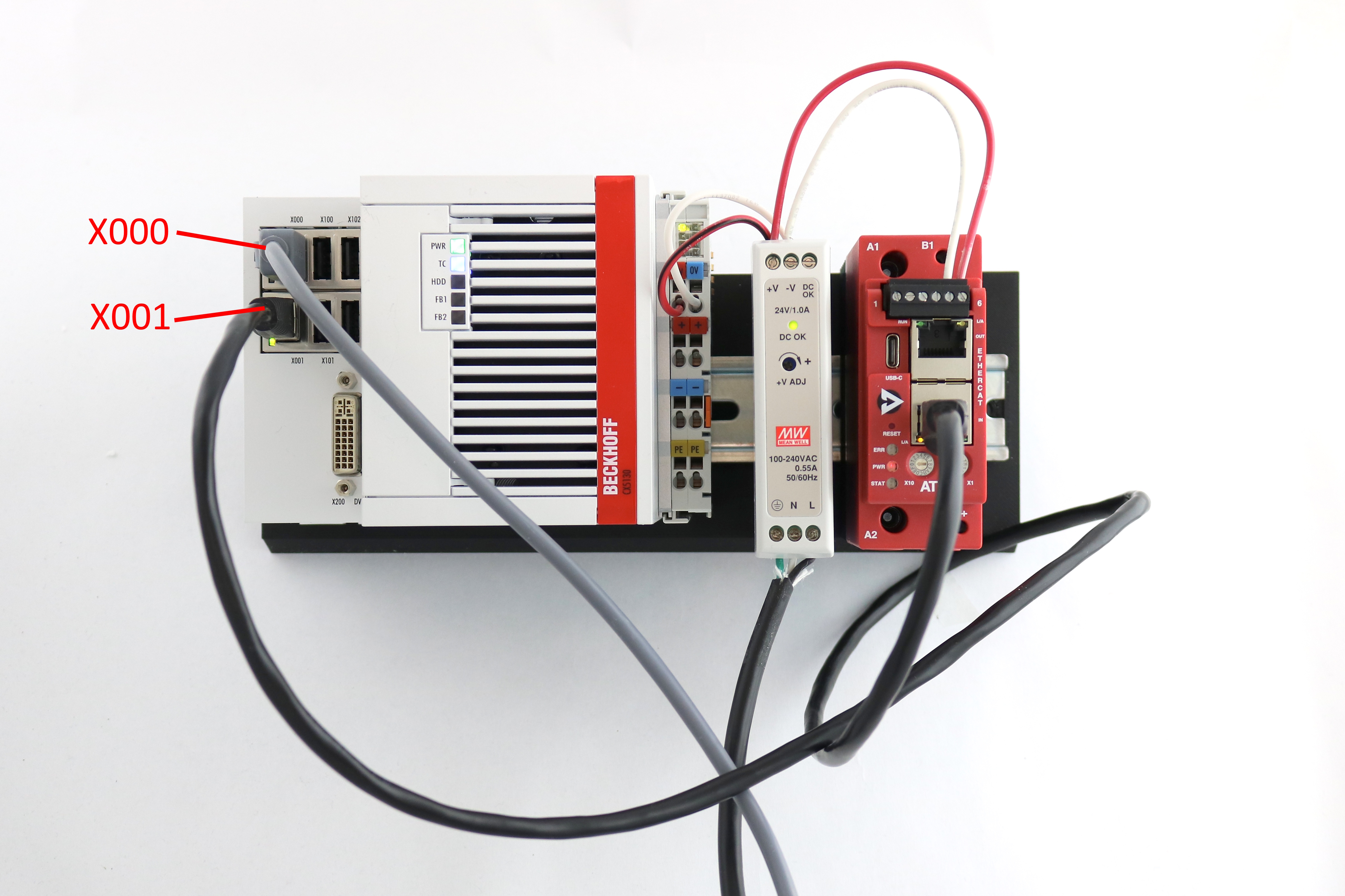
Connections:
- Connect port
X000on your PLC to your PC with an Ethernet cable. - Connect port
X001on your PLC to theINport on ATOM with an Ethernet cable. - Connect 24V DC power to ATOM and your PLC.
PLC configuration
You can skip this section if you are using the TwinCAT soft PLC simulator.
- If you are using a PLC, connect a monitor and keyboard to it and power it on.
- Open Network Connection Manager, right-click the
X000network interface, and select Properties:
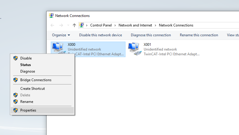
- In the X000 Properties dialog, select Internet Protocol Version 4 (TCP/IPv4) and click Properties:
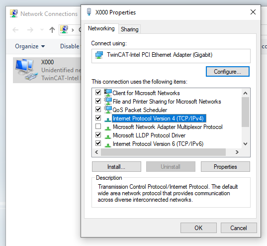
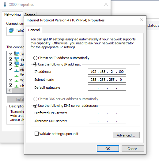
- In the Internet Protocol Version 4 (TCP/IPv4) Properties dialog, select Use the following IP address and enter the following values. Then click OK:
- IP address:
192.168.2.100 - Subnet mask:
255.255.255.0
- IP address:
PC configuration
Back on your PC, follow these steps:
This uses a network adapter named EtherCAT Network to make it easy to remember and follow along. If your network adapter has a different name, use that instead.
-
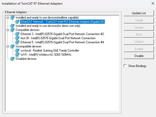
Navigate to your TwinCAT 3 installation directory (typically
C:\TwinCAT\3.1\System) and executeTcRteInstall.exe. Ensure that the network adapter you intend to use appears under the Installed and ready to use devices(realtime capable) category. If it does not, select the network adapter and click Install:
-
Place
Atom.xml(from the requirements section) in theC:\TwinCAT\3.1\Config\Io\EtherCATdirectory. This is where TwinCAT looks for ESI files. -
Navigate to your Settings app and locate your
EtherCAT Networkadapter. Right-click it and select Edit:
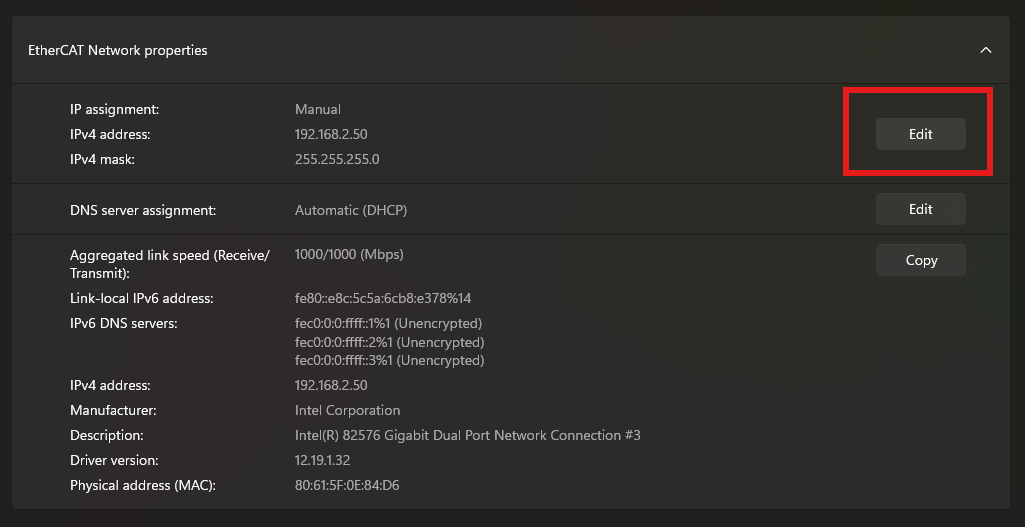
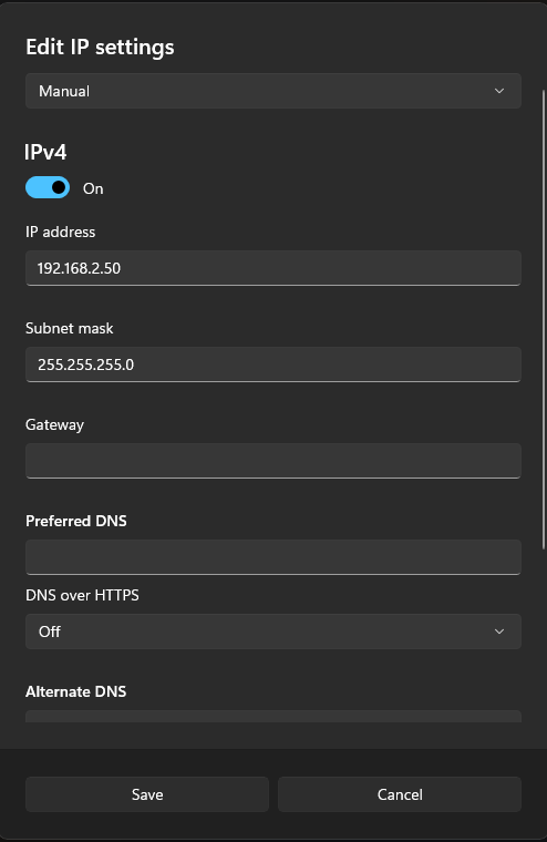
- In the EtherCAT Network Properties dialog, set the
IP addressandSubnet maskto the following values. Then, hit Save.- IP address:
192.168.2.50 - Subnet mask:
255.255.255.0
- IP address:
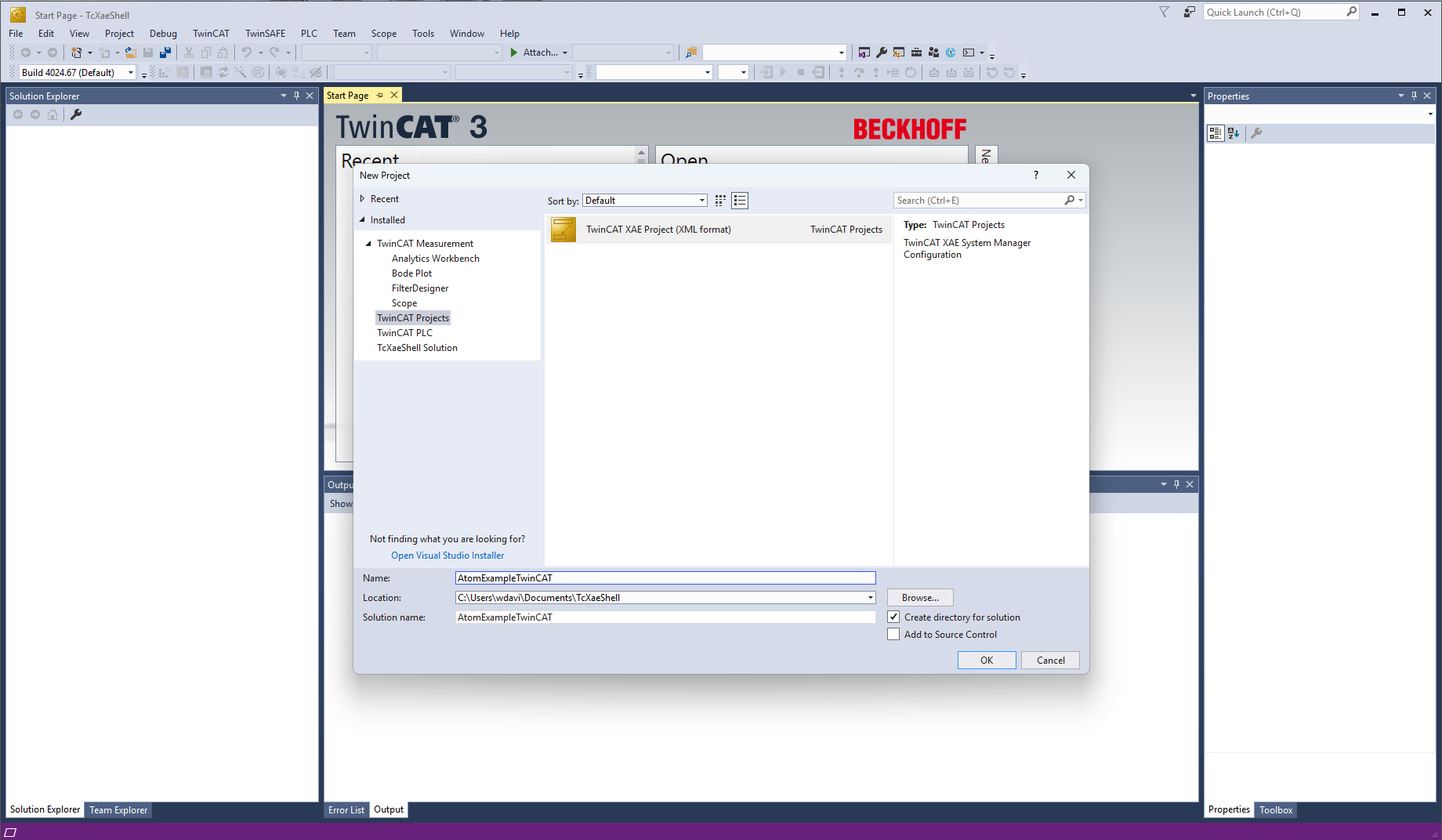
Creating a TwinCAT 3 project
- Open TwinCAT 3 and select File > New Project. Name it
AtomExampleTwinCATand click OK:
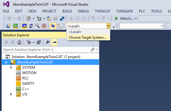
Connecting to your PLC
If you are using the TwinCAT soft PLC simulator, you can skip this section.
- Select the target dropdown and click Choose Target System...:
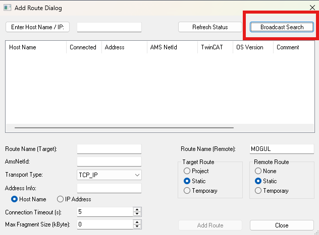
- Click Search (Ethernet):

- Select Broadcast Search:
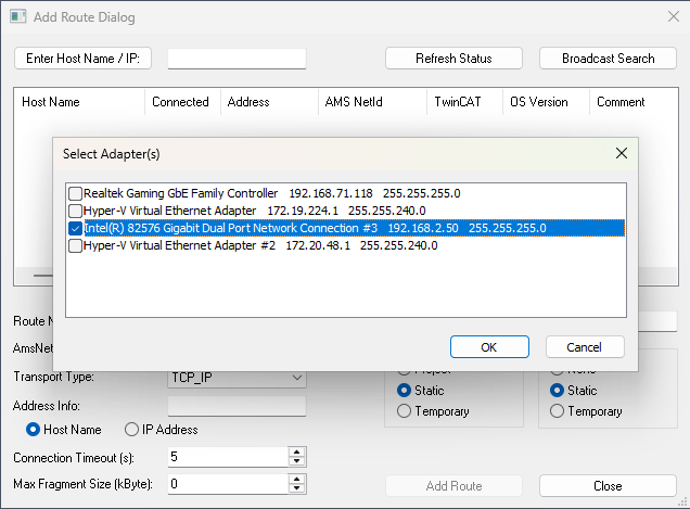
- Select the network adapter to search - pick the one labeled
192.168.2.50:
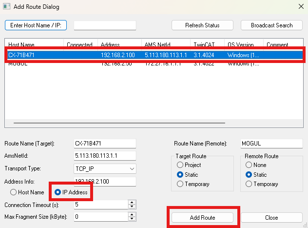
- Select your
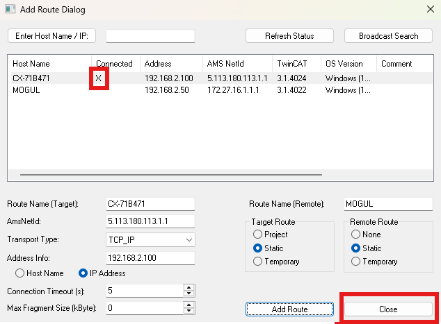
PLCfrom the list (it should have the IP address you configured above:192.168.2.100). Under Address Info select IP Address, then click Add Route:
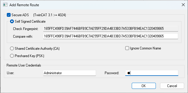
- If you want to use
Secure ADS, checkSecure ADSand copy theCheck Fingerprintvalue to theCompare withbox. In Remote User Credentials, enter the username and password for your PLC, then click OK. If you haven't changed it, the default Beckhoff credentials are:- Username:
Administrator - Password:
1
- Username:
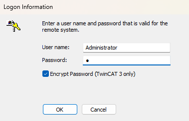
- If a password prompt appears, enter the same username & password for your PLC as in step 6. then click OK:
- If everything worked correctly, you should see a check or X under the
Connectedcolumn next to your PLC. If it does, hit Close:
- Select the target dropdown and select your PLC (in our case,
CX-71B471):
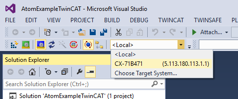
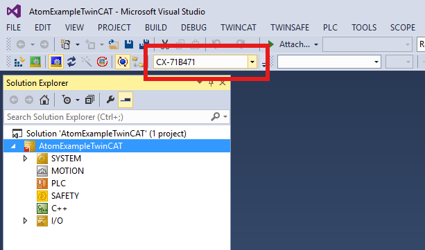
- If everything worked correctly, you should see
CX-71B471become the value in the dropdown with no(ERROR)suffix:
Adding and configuring Atom
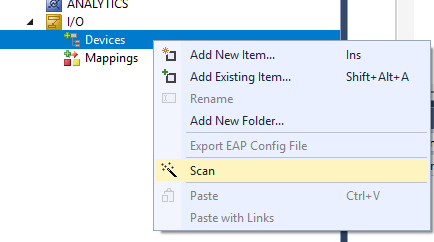
- Right-click I/O > Devices and select Scan:
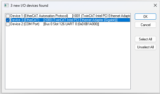
- Select the entry that reads
Device 3 (EtherCAT)and click OK (this might be slightly different for you):
- When prompted to Scan for boxes, select Yes:

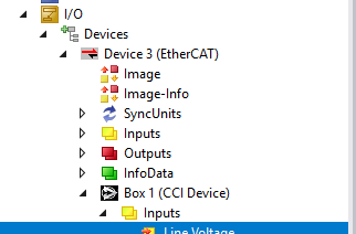
- If everything worked correctly, you should see
Device 3 (EtherCAT)(your PLC) andBox 1 (CCI Device)(ATOM) in the I/O Devices tree. If you do not, see troubleshooting.
If you are using the TwinCAT soft PLC simulator, you should only see Box 1 (CCI Device) in the I/O Devices tree.
Configuring your TwinCAT 3 project
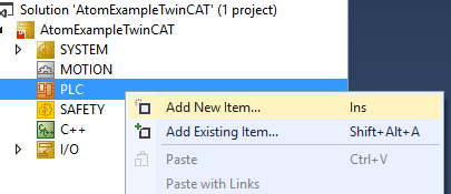
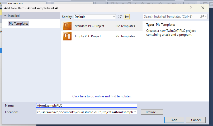
- Right-click PLC and select Add New Item...:
- Select Standard PLC Project, name it
AtomExamplePLC. Click Add:
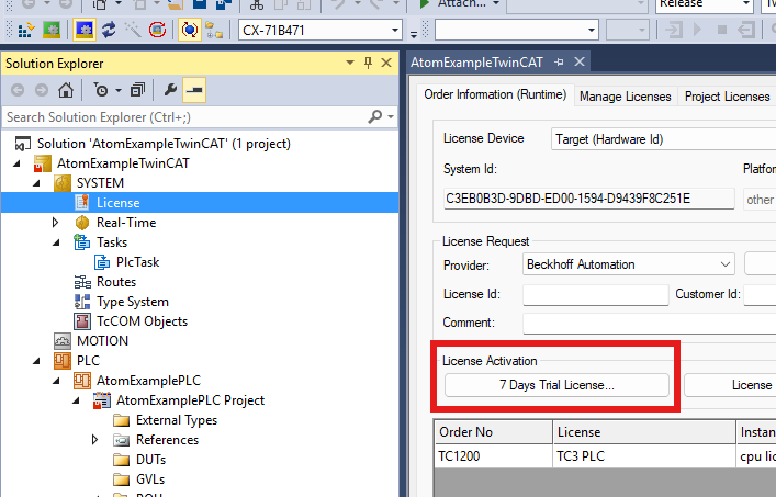
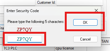
- Select License and click **7 Days Trial License...*. Then complete the CAPTCHA:
- Select Device 3 (EtherCAT) and click Sync Unit Assignment:
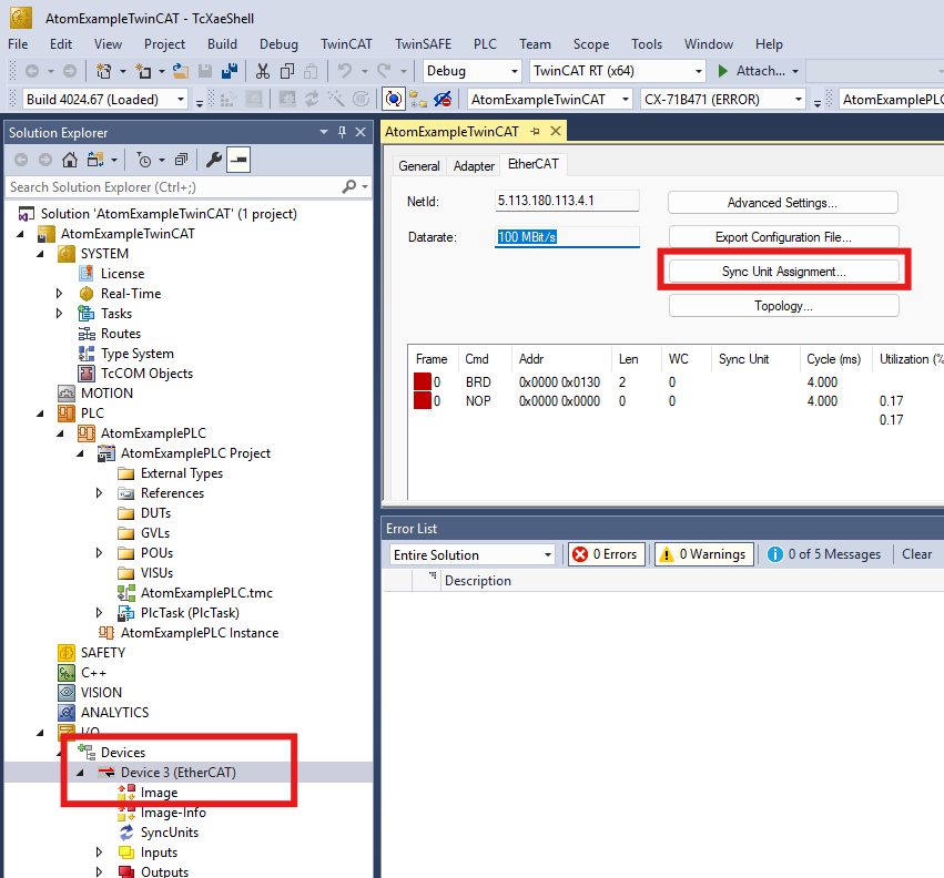
- Select PlcTask and hit Apply:
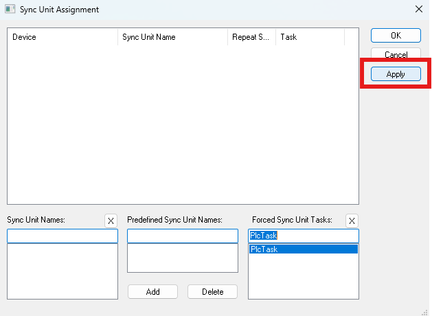
If you get an error message like "needs sync master (at least one variable linked to a task variable)", redo this step.
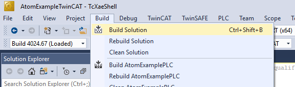
- Select Build > Build Solution. If you configured everything correctly, you should see a message like
Build succeededin the lower left and no error messages should pop up:

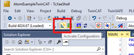
Crash course in TwinCAT 3
Most actions can be performed from the TwinCAT menu in the top bar. Here are some of the most common actions:
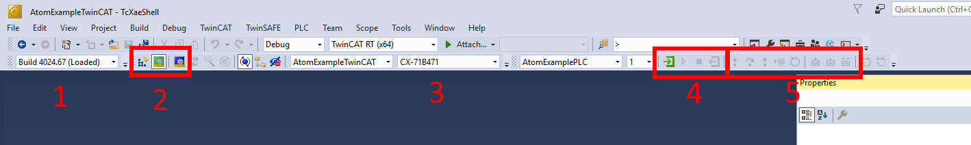
1- The TwinCAT build version to use. This should match the version of TwinCAT on your PLC.2- From left to right:Activate the configuration: Loads the PLC project onto the PLC as the boot project (the project the PLC will auto-start when it boots)Run: Puts the TwinCAT system into run mode, allowing the PLC to execute the projectConfig: Puts the TwinCAT system into configuration mode, allowing you to modify the PLC project.- You may occasionally get a prompt reading
Activate free run?- free run is a special PLC mode that allows you to edit EtherCAT variables on your I/O devices manually without having to put the PLC into run mode. - When adding new devices or installing new ESI files, you may need to click activate config mode even if config mode is already active. Clicking Config mode will restart the PLC in config mode.
- You may occasionally get a prompt reading
3- This is the PLC you want to program.<Local>is the built in soft PLC for testing & development.4: From left to right:Login- Log in to download changes to the PLC and debug in real-time.Start- Start PLC program execution.Stop- Pause PLC program execution.Logout- Log out of the PLC to make changes/modify the PLC program.
5: Debugging tools. You can set breakpoints, step through code, force variables, and more.
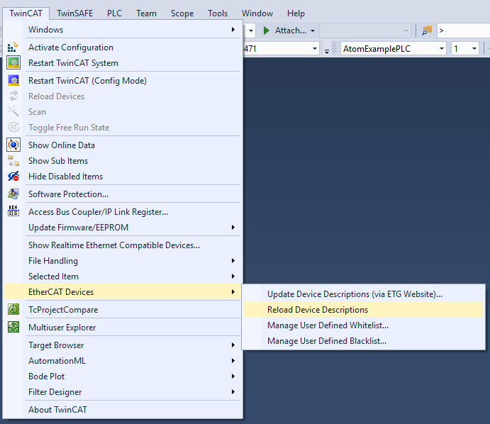
If you install a new ESI file in C:\TwinCAT\3.1\Config\Io\EtherCAT, you may need to Reload Device Descriptions and restart the PLC in config mode:
When you login to the PLC, you may be prompted with this dialog:
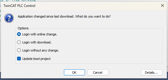
Login with online change- Changes you made to the project with be pushed in real-time to the PLC without restarting the current program. Essentially, this pushes the "delta-updates".Login with download- The entire project is re-downloaded to the PLC, overwriting & restarting whatever program was running.Login without any change- Do not download any changes you made to the PLC.Update boot project- Update the default boot project to the one you are downloading.
A basic example program
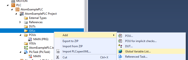
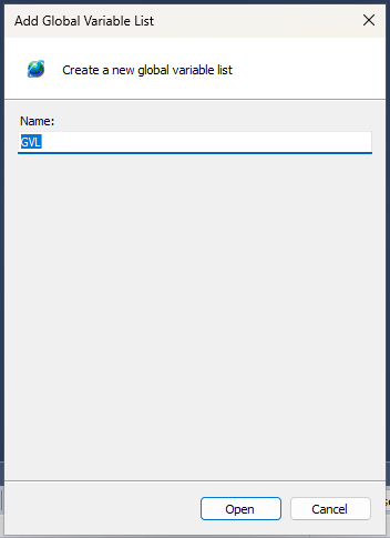
- Right-click GVLs and select Add > Global Variable List. Name it
GVLand click Add:
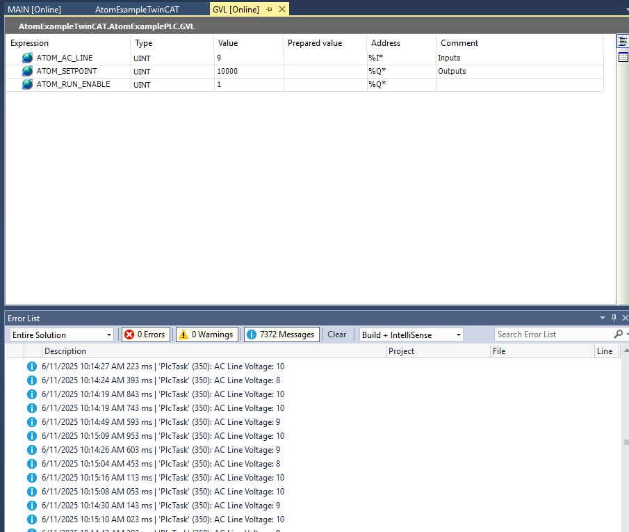
- Create three variables:
  // Inputs
  ATOM_AC_LINE AT %I* : UINT; // AC Line Voltage in Volts as reported by ATOM

  // Outputs
  ATOM_SETPOINT AT %Q* : UINT; // The setpoint/output command to ATOM
  ATOM_RUN_ENABLE AT %Q* : UINT; // Put ATOM in RUN/STOP
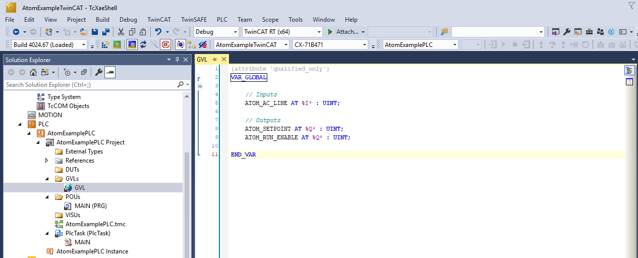
Global variables take the format:
<NAME> AT %<I/Q>* : <DATA-TYPE>;. Use %I* for inputs and %Q* for outputs. All ATOM EtherCAT variables are UINT (unsigned integers).
- You must build the project to register the global variables. Select Build > Build Solution. If you configured everything correctly, you should see a message like
Build succeededin the lower left and no error messages should pop up:
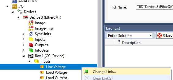
- Right-click
Box 1 (CCI Device)>Inputs>Line Voltageand select **Change Link...*:
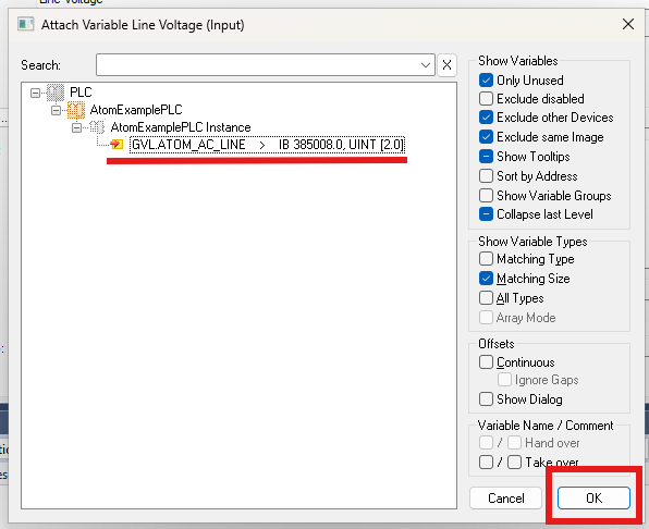
- Select the corresponding global variable
GVL.ATOM_AC_LINEand click OK:
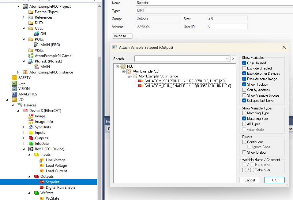
- Repeat the process for
Outputs>SetpointandOutputs>Digital Run Enable:
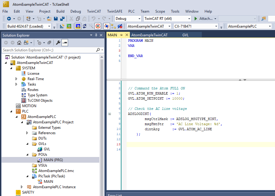
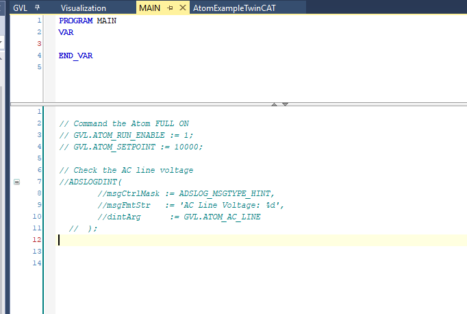
- Select the main program
MAIN (PRG)and add the following code:
// Command the Atom FULL ON
GVL.ATOM_RUN_ENABLE := 1;
GVL.ATOM_SETPOINT := 10000;

// Print the AC line voltage:

ADSLOGDINT(
  msgCtrlMask := ADSLOG_MSGTYPE_HINT,
  msgFmtStr := 'AC Line Voltage: %d V',
  msgArgs := GVL.ATOM_AC_LINE
);
- Activate the configuration:
- Check Autostart PLC Boot Project(s) and click OK:

- When prompted to Restart TwinCAT System in Run Mode, click Yes:

- Login to the PLC by clicking the Login button in the top bar. You should see the AC Line Voltage updated in the debug window and printed to the console:

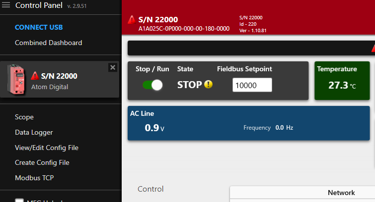
Additionally, if you connect to ATOM with Control Panel over USB, you can see the ATOM went into RUN mode and the output setpoint was set to 10000 (which is 100.0% of the output):
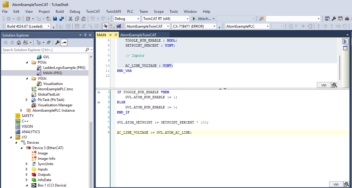
Once you've verified that ATOM is working, you can comment out the code in MAIN (PRG):
Next, we'll create a simple user interface to control ATOM. You can follow along with either the Structured Text or Ladder Logic examples below.
Structured Text
- Define the variables:
// Outputs

TOGGLE_RUN_ENABLE : BOOL;
SETPOINT_PERCENT : UINT;

// Inputs

AC_LINE_VOLTAGE : UINT;
Add the following code:
IF TOGGLE_RUN_ENABLE THEN
	GVL.ATOM_RUN_ENABLE := 1;
ELSE
	GVL.ATOM_RUN_ENABLE := 0;
END_IF

GVL.ATOM_SETPOINT := SETPOINT_PERCENT * 100;

AC_LINE_VOLTAGE := GVL.ATOM_AC_LINE;
Next, head to the interface section to create a simple user interface to control ATOM.
Ladder logic
Right click POUs and select Add > POU...
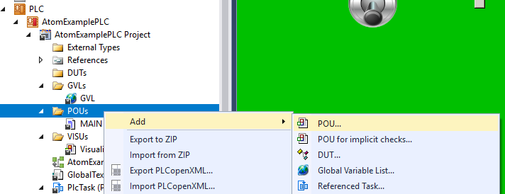
Set the name to LadderLogicExample, set type to Program and select Ladder Logic Diagram (LD) as the Implementation language:
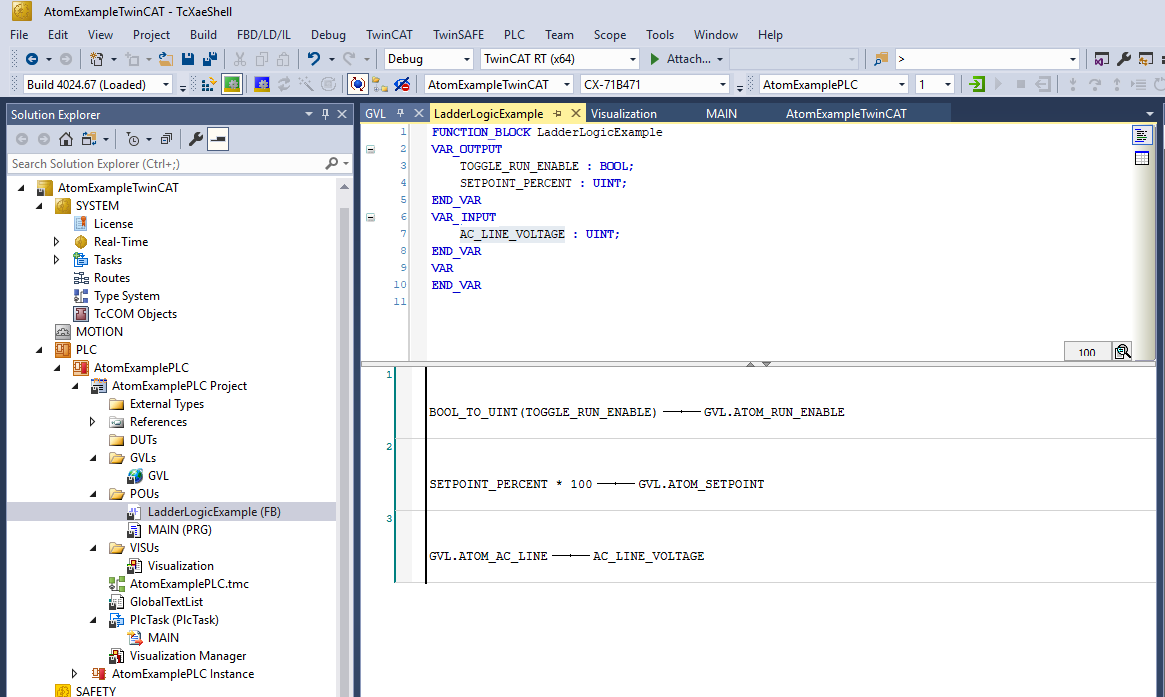
Copy the following code into the top panel of the LadderLogicExample editor:
// ...
VAR_OUTPUT
	TOGGLE_RUN_ENABLE: BOOL;
  SETPOINT_PERCENT : UINT;
END_VAR

VAR_INPUT
	AC_LINE_VOLTAGE : UINT;
END_VAR
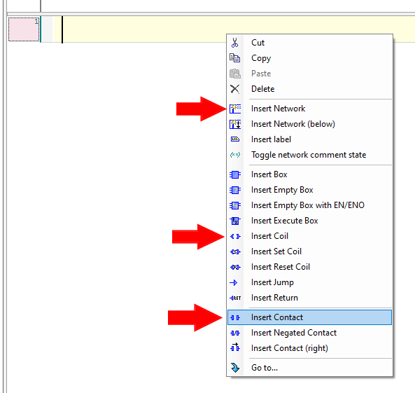
In the bottom panel of the editor, we'll create a simple ladder logic program using the variables we just added above.
- Create 3 networks total by right-clicking and selecting Insert Network
- For each network, right click and insert one contact and one coil
After you're finished, your ladder logic program should look like:

For each rung, replace the ??? with the corresponding variables:
- Rung #1 -
BOOL_TO_UINT(TOGGLE_RUN_ENABLE)andGVL.ATOM_RUN_ENABLE - Rung #2 -
SETPOINT_PERCENT * 100andGVL.ATOM_SETPOINT - Rung #3 -
GVL.ATOM_AC_LINEandAC_LINE_VOLTAGE
After you're finished, your ladder logic program should look like:
Next, head to the interface section to create a simple user interface to control ATOM.
Creating a user interface
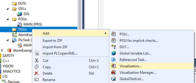
- Right click VISUs and select Add > Visualization...:
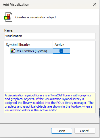
- Name it
Visualizationand check Active onVisuSymbols (System), then hitOpen:
- Select components in to the toolbox on the right and drag them onto the canvas:
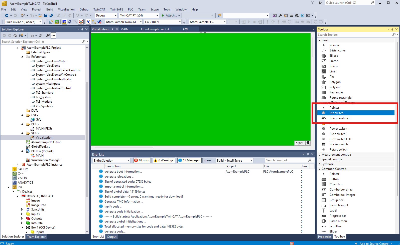
- In this example, we will add:
- A Dip switch to toggle the
Run Enablestate - A Slider to set the output setpoint percentage
- A Meter to display the AC line voltage
- A Dip switch to toggle the
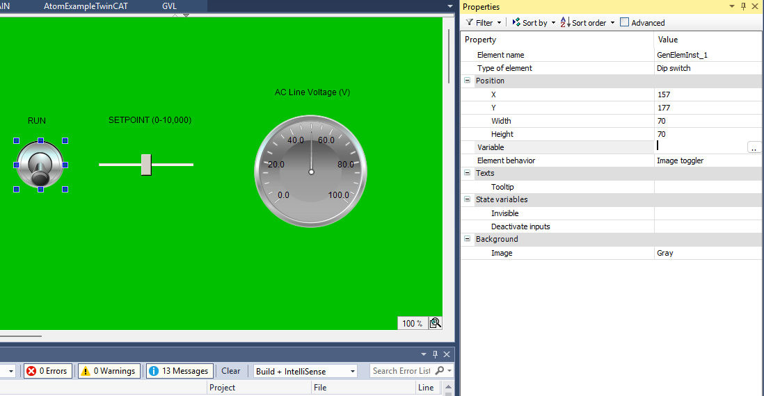
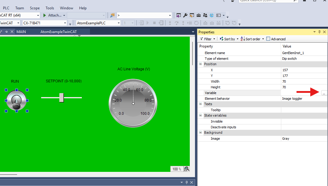
- Connect the components to the variables we defined earlier:
- For the Dip switch, set the
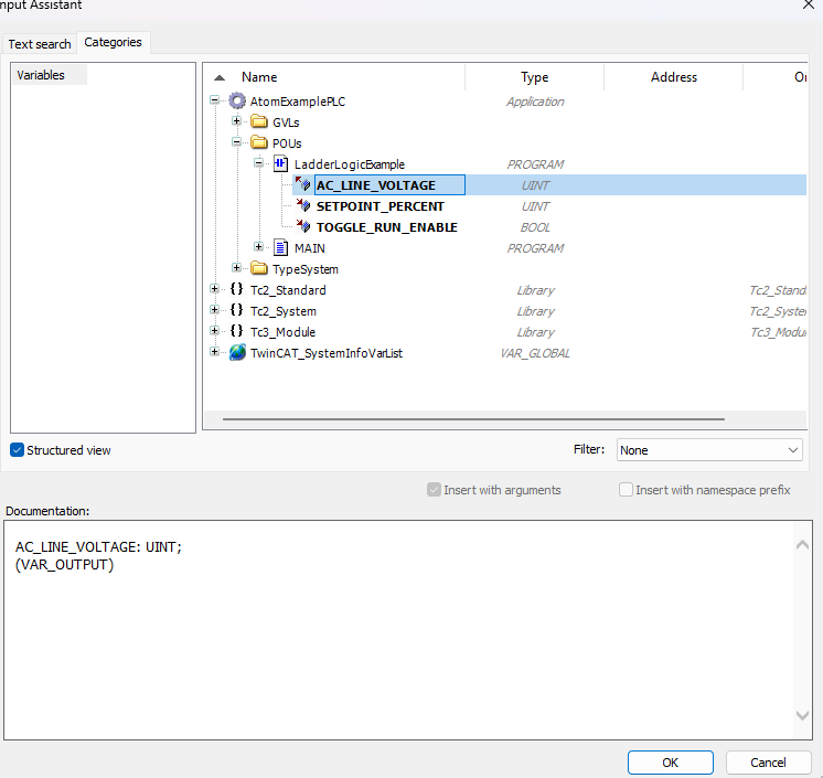
Variableproperty toMAIN.TOGGLE_RUN_ENABLE, if using structured text, orLadderLogicExample.TOGGLE_RUN_ENABLEif using ladder logic. - For the Slider, set the
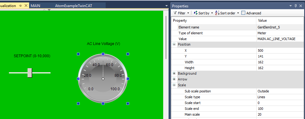
Variableproperty toMAIN.SETPOINT_PERCENT, if using structured text, orLadderLogicExample.SETPOINT_PERCENTif using ladder logic. - For the Meter, set the
Valueproperty toMAIN.AC_LINE_VOLTAGEif using structured text, orLadderLogicExample.AC_LINE_VOLTAGEif using ladder logic.
- For the Dip switch, set the
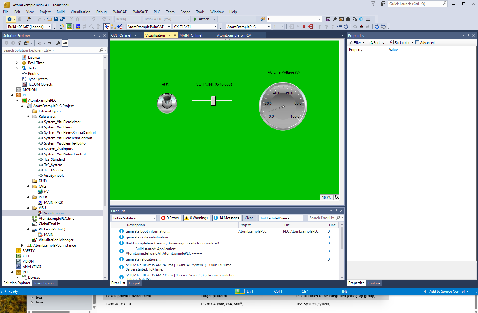
- Build the project and hit Login. Select Login with online change and click OK:
- If everything worked correctly, you should see the ATOM's AC line voltage in the meter, and you can toggle the run enable state and set the output setpoint percentage using the dip switch and slider, respectively:
Troubleshooting
- My ATOM does not appear in the TwinCAT I/O Devices tree.
- Ensure that ATOM is powered on and connected to the same network as your PC.
- Check that the
Atom.xmlfile is in the correct directory:C:\TwinCAT\3.1\Config\Io\EtherCAT. - Ensure that you have installed the ESI file correctly and reloaded the device descriptions in TwinCAT.
- Check the network cable connection between your PC, ATOM, and PLC.
- I cannot connect to my PLC.
- Ensure that the PLC is powered on and connected to the same network as your PC.
- Check that you have configured the correct IP address and subnet mask for both the PLC and your PC.
- Ensure that you have the correct username and password for your PLC.
- My variables are missing or an ESI file is working:
- Select Reload Device Descriptions from the TwinCAT menu bar.
- Click Config to restart the PLC in config mode.
- Select the Activate the configuration button in the TwinCAT menu bar.
Can't connect to PLC or ATOM
Use the ping utility on Windows to check if your PC can reach the PLC/ATOM:
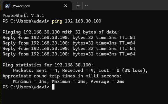
If:
- Ping is successful - you have a configuration problem with your PC
- Ping is unsuccessful - you have a hardware configuration, PLC configuration, or ATOM configuration problem.
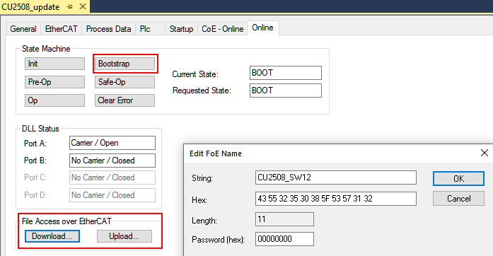
Advanced
ATOM supports FOE (File Over EtherCAT) for firmware updates. If you receive a firmware update file from Control Concepts, you can update ATOM's firmware using TwinCAT 3: