Labview
You do NOT need to purchase the NI-Industrial Communications for EtherNet/IP add-on.
This is only used if you want your Labview application to operate as an EtherNet/IP adapter device. In our case, Labview will operate as a scanner that connects to ATOM to control it. This functionality is included in the default version of Labview.
We use explicit messaging to connect to ATOM from Labview because Labview does not support I/O connections.
Using our pre-built VI
Download our ATOM control panel VI to quickly control and monitor ATOM from Labview.
Most of the parameters listed in our EtherNet/IP Profile are available through the VI controls, although you can easily extend or alter the VI to suite your needs.
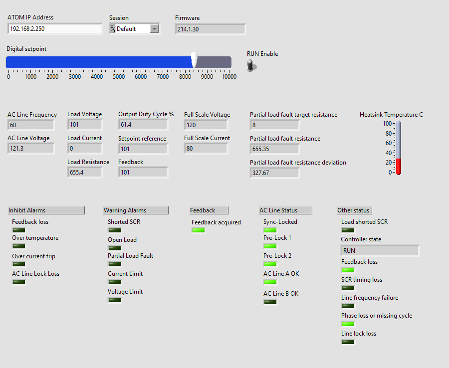
To setup the VI, enter the IP address of your ATOM unit in the ATOM IP Address box. Below, we've entered 192.168.2.250 as the IP address. You can check or change
your ATOM's IP address by using Control Panel.
After you've set the IP address, you can run the VI by clicking the run icon:

After the VI starts, you can adjust the Digital setpoint and RUN Enable controls. All the other indicators will update every 500 ms to reflect the current state of the ATOM unit.
Advanced
Reading and parsing data from ATOM
If you need to modify or extend the VI that we provide, this section is provided to help make it easier.
The main way to pull data from ATOM is by fetching the producing assembly object (class 4, instance 102, attribute 3) using the Get Attribute Single service (0x0E).
Below is a simple example of fetching ATOM's assembly object. After this block diagram executes, Out data will be a byte array of length 86 containing
the 30 parameters listed in ATOM's EtherNet/IP Profile:

To pull a parameter out of this byte array, you can calculate its index within Out data by finding the sum of the parameter data type sizes before it.
To pull out the AC Line Voltage parameter, we can calculate the sum of the parameter data type sizes before it. AC Line Voltage is parameter #7, so we sum the size of the first 6 parameters, which each have sizes of:
Digital setpoint = DINT = 4 bytes
Digital run enable = BOOL = 1 byte
Inhibit alarm status = BYTE = 1 byte
Warning alarm status = BYTE = 1 byte
Feedback read setatus = BOOL = 1 byte
AC Line Frequency = REAL = 4 bytes
Summing these up, we get:
4 (DINT) + 1 (BOOL) + 1 (BYTE) + 1 (BYTE) + 1 (BYTE) + 4 (REAL) = 12
AC Line Voltage itself is a REAL, so AC Line Voltage resides at index 12 within Out data and extends for 4 bytes.
To properly display this within your VI, you will need to reverse the order of these four bytes before interpreting them as a single precision decimal in Labview. This is because Labview is by default big-endian, while ATOM is little-endian.
Writing data to ATOM
Below is a simple diagram that updates the digital setpoint parameter on ATOM.
An alternative method to this one is to compile together an assembly object and use the Set Attribute Single service (0x10) to write to the consuming assembly object (class 4, instance 101, attribute 3). The one downside to this is that it requires you to send all parameters within the consuming assembly object together.
Instead, we provide the custom ParameterLink object (class 100, instance i, attribute 1), where i is the parameter number you wish to interact with.
Below, we write to ParameterLink instance 1, attribute 1. Consult the EtherNet/IP Profile to determine the data type of the parameter you wish to
write. Here, we're writing digital setpoint, which is a DINT, so we'll make sure that we use an i32 in Labview. Note that before we write the data,
we have to reverse the bytes as Labview is by default big-endian, while ATOM is little-endian:
