RSLogix Studio 5000
Overview
In this tutorial, you'll learn how to control ATOM over EtherNet/IP with RSLogix Studio 5000.
If you'd like to skip this tutorial, download the completed example project: AtomExampleStudio5000.zip.
Prerequisites
- A PC with RSLogix Studio 5000 installed (See Installation Troubleshooting for help with installation issues):
- A Logix PLC - a CompactLogix
1769-L19ER-BB1Bis used in this example, but you can follow along with any Logix PLC that supports EtherNet/IP. - Download ATOM's EDS file: Atom.eds
Hardware Setup
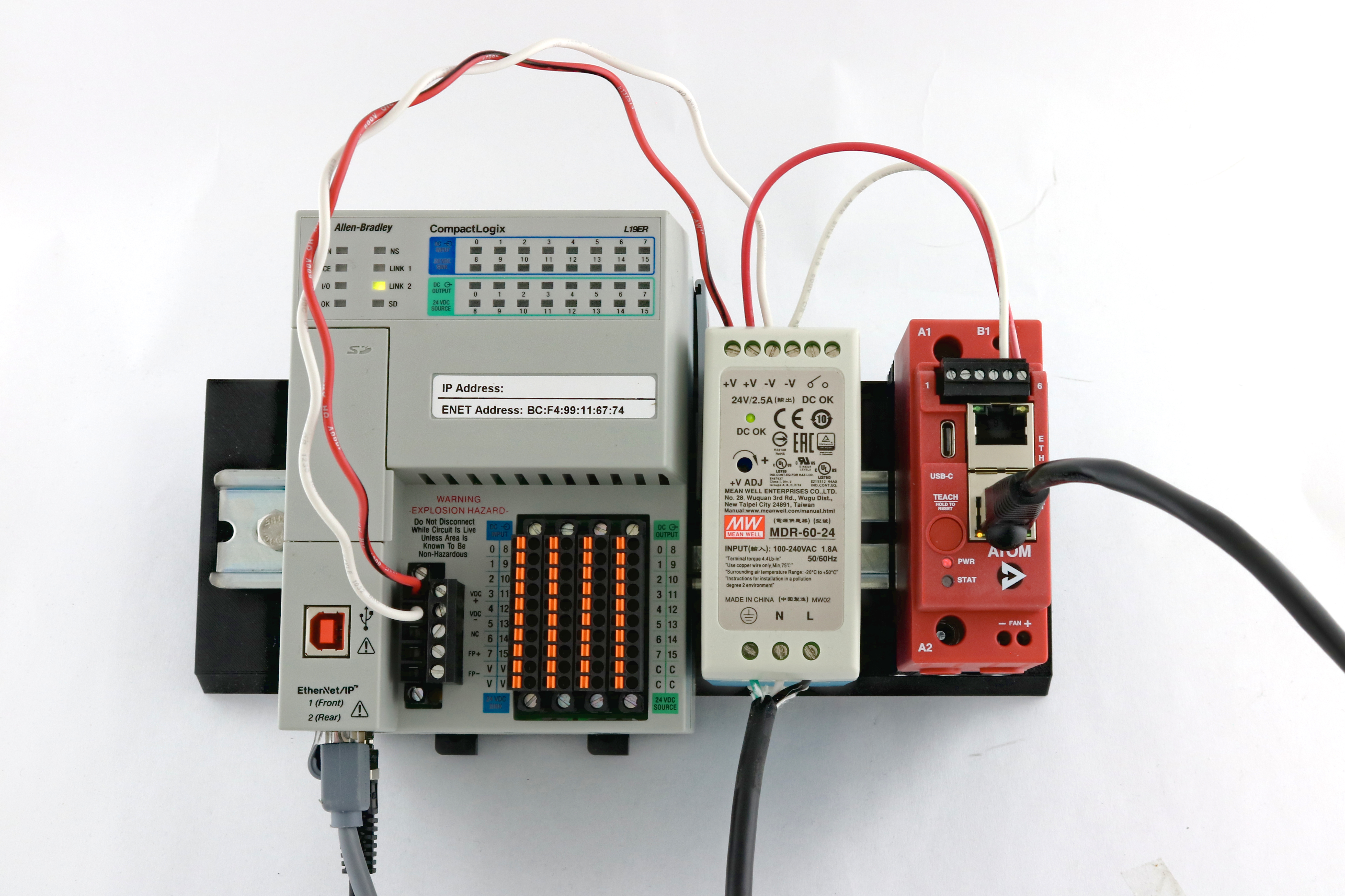
Connections:
- Connect port
1 (Front)on your PLC to your PC - Connect port
2 (Rear)on your PLC to ATOM (either port) - Connect a 24VDC power supply to ATOM and your PLC
PLC Configuration
Upgrading firmware
Make sure to upgrade your PLC firmware to the lastest version to ensure compatibility with Studio 5000.
- Connect your Logix PLC to your PC with a USB cable.
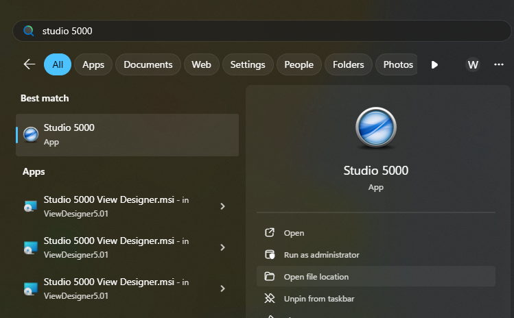
- Launch
ControlFLASH Plus:

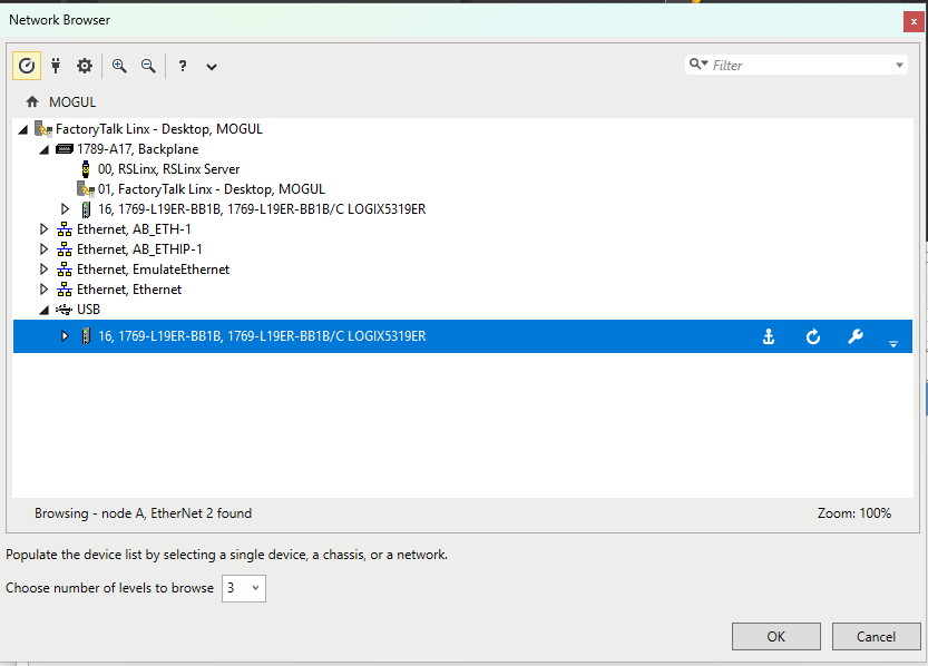
- Open the network browser:

- Select your PLC under the
USBcategory:
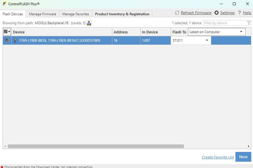
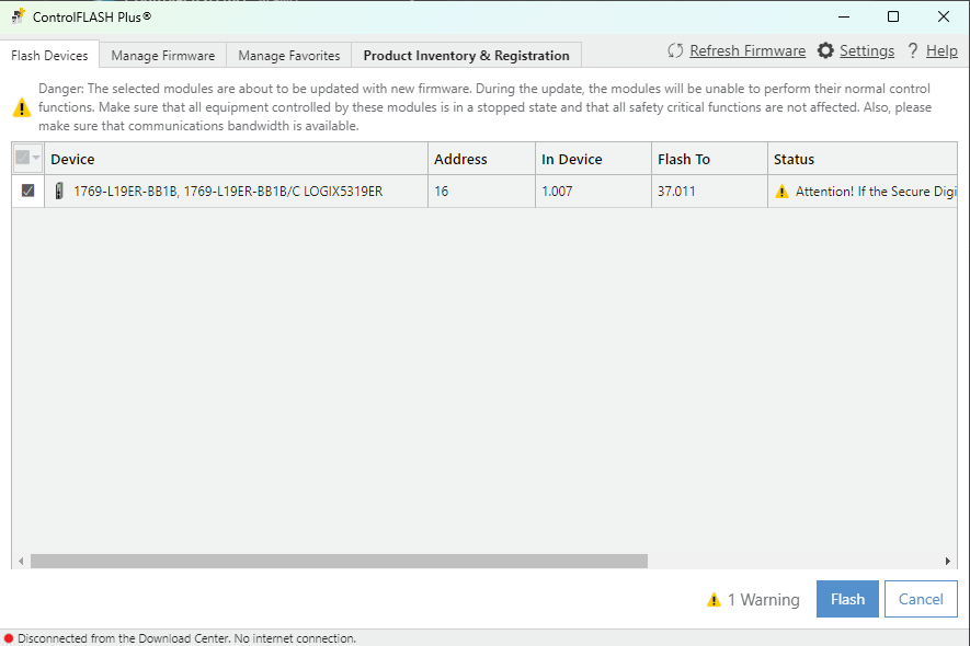
- Select the device and latest firmware version, then click Next:
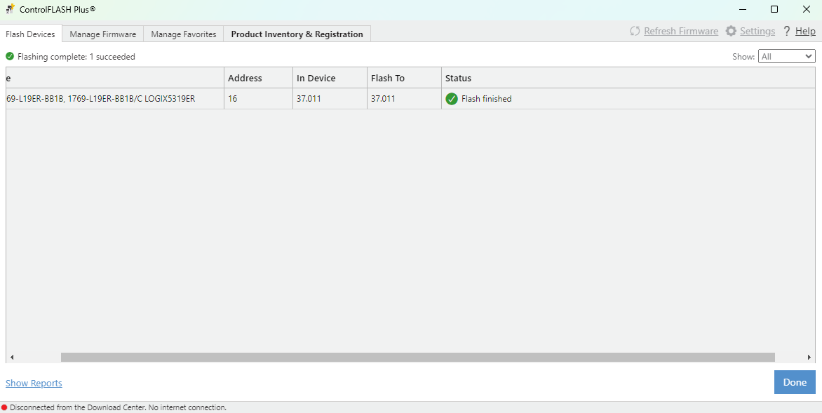
- Click Flash:
- After flashing succeeds, reboot your PLC.
Configuring your PC's network settings
- Open your PC's network settings and select edit on the Ethernet adapter connected to your PLC:
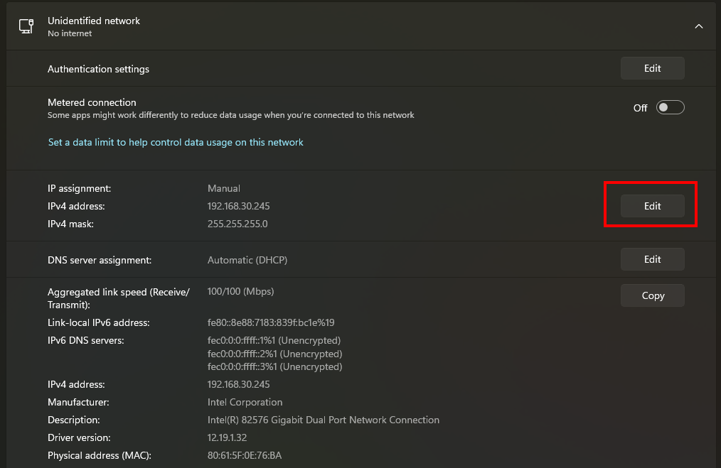
-
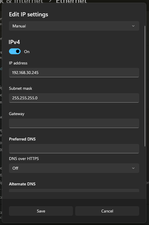
In the Edit IP Settings dialog, set:
- IP Address:
192.168.30.245 - Subnet Mask:
255.255.255.0
Click Save to apply the settings.
- IP Address:
-
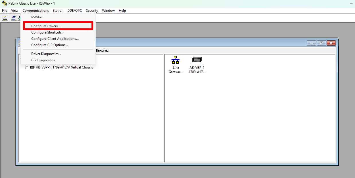
Open RSLogix Classic and select Communications > Configure Drivers:
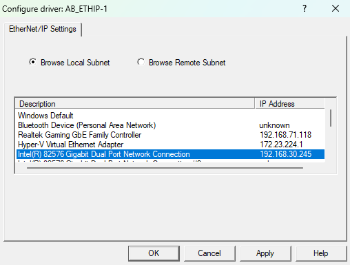
- Select EtherNet/IP Driver and click Add New:

- Click OK to add the driver:

- Select the adapter with IP address
192.168.30.245, then hit Apply and OK:
ATOM Configuration
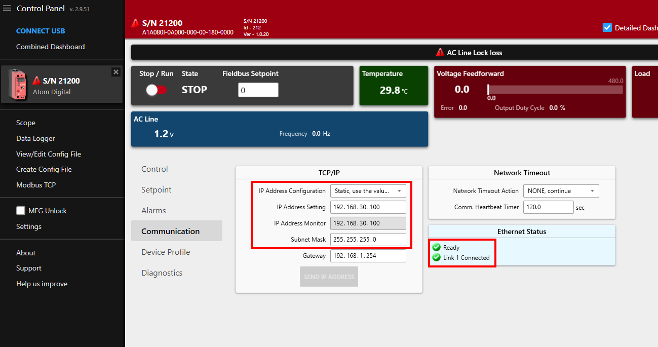
- Connect ATOM to your PC using a USB-C cable. Launch Control Panel and connect to your ATOM. In the Network tab, set the following:
- IP Address Configuration:
Static - IP Address:
192.168.30.100 - Subnet Mask:
255.255.255.0
- IP Address Configuration:
Create a Studio 5000 project and connect to your PLC
- Launch Studio 5000, select File > New Project. Name the project
AtomExampleStudio5000and select1769-L19ER-BB1B(CompactLogix 5370). Click OK:

- Select
0 Modulesunder Expansion I/O, then click Finish:

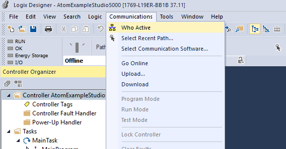
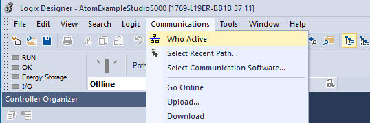
- Connect your PLC to your PC with a USB-B cable. In Studio 5000, select Communications > Who Active:
- Select your PLC under the USB category and click Go Online:

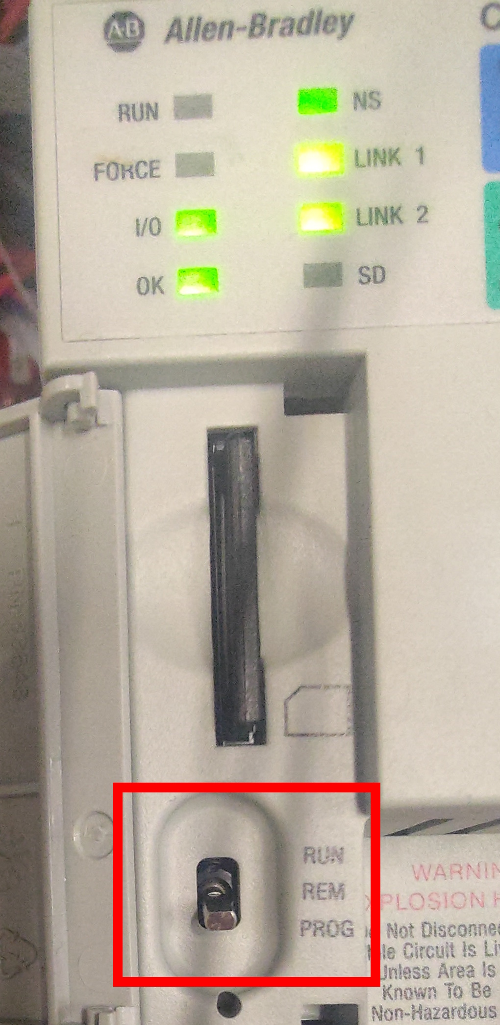
Ensure the switch on your PLC is set to
PROGmode before downloading.
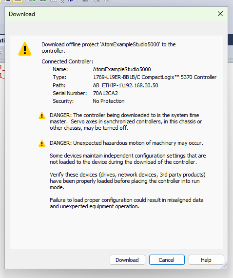
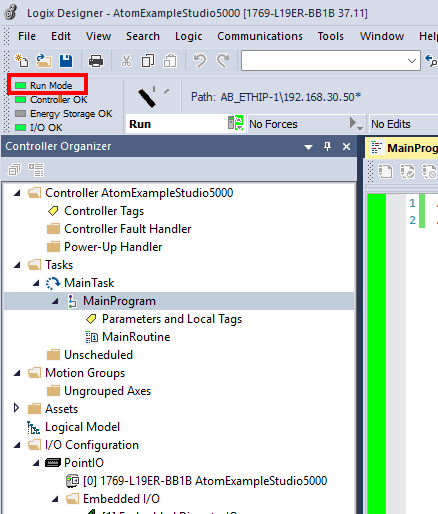
- Select Download and double check that the
Controller OKindicator light turns green:


- Right click
Controller AtomExampleStudio5000and select Properties:

- In the Internet Protocol tab, set the following and hit Apply and OK:
- Manually configure IP settings checked
- IP Address:
192.168.30.50 - Subnet Mask:
255.255.255.0

- Disconnect the USB cable from your PLC. In Studio 5000, select Communications > Who Active again, then select your PLC under the Ethernet category and click Go Online:

You should also see ATOM (with IP address
192.168.30.100) under theAB_ETHIP-1category.
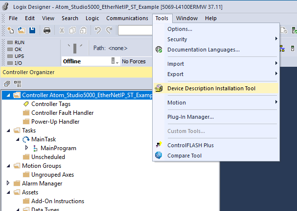
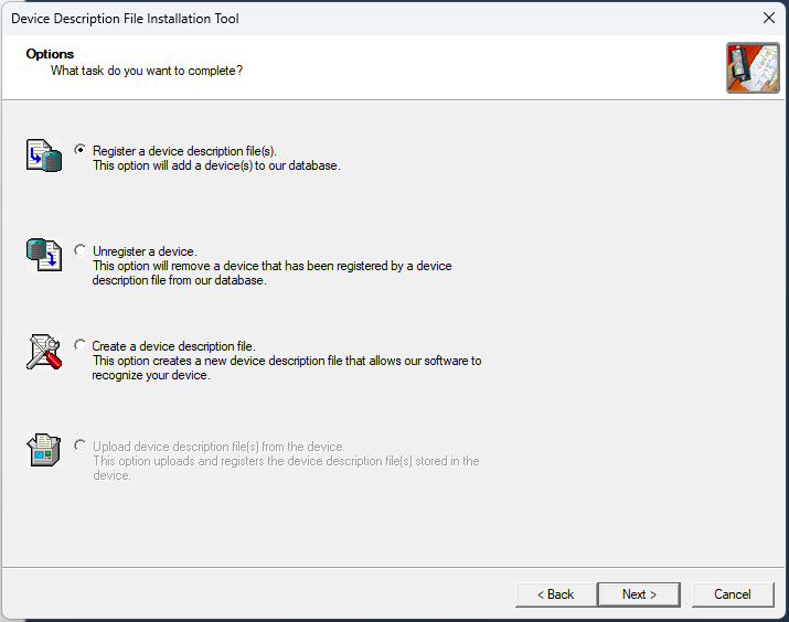
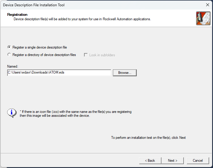
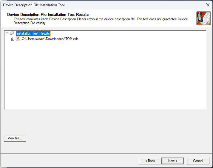
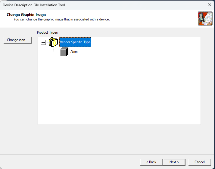
Import EDS file
Select Tools > Device Description Installation Tool (some versions call it EDS Hardware Installation Tool)
Add Atom to the project
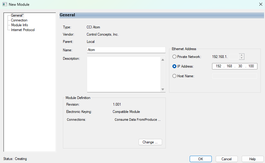
- Right-click Ethernet and select New Module:

- In the Catalog tab, search for
Atom, select it, and click Create:

- In the General tab, set the IP Address to
192.168.30.100and click OK:
A basic example program
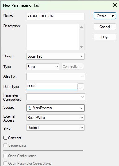
- Right-click Parameters and Local Tags under
MainProgramand select New Tag to create a tag:

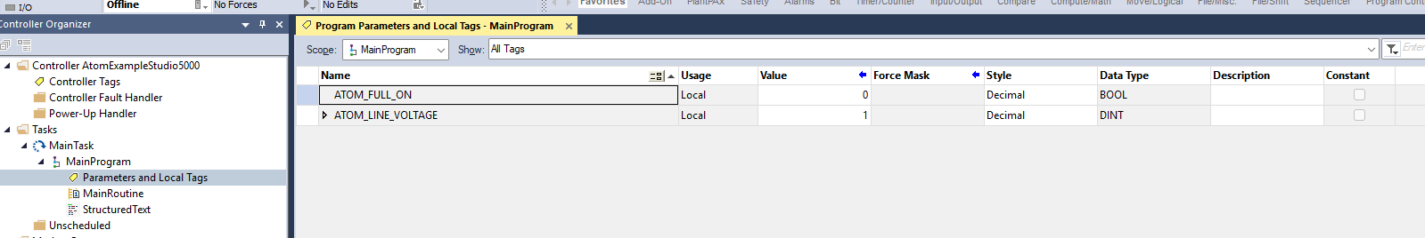
- Create two_ new tags:
- Tag 1
- Name:
ATOM_FULL_ON - Data Type:
BOOL
- Name:
- Tag 2
- Name:
ATOM_LINE_VOLTAGE - Data Type:
DINT
- Name:
- Tag 1
You can follow along with either the Structured Text or Ladder Logic examples below.
Ladder Logic
- In the
MainRoutinefile, selectRing 0and add anExamine Oninstruction:
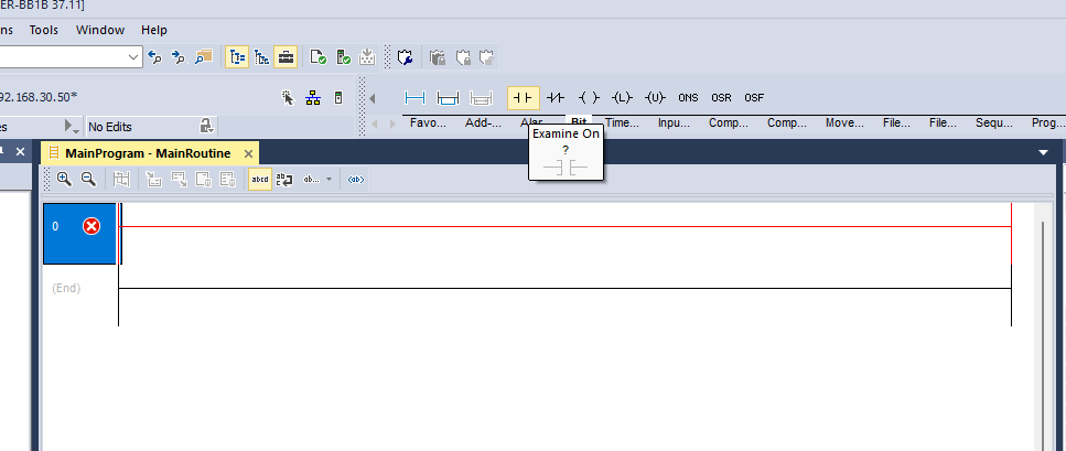
- Configure this instruction to examine the
ATOM_FULL_ONtag:
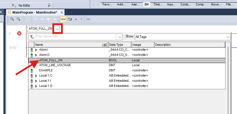
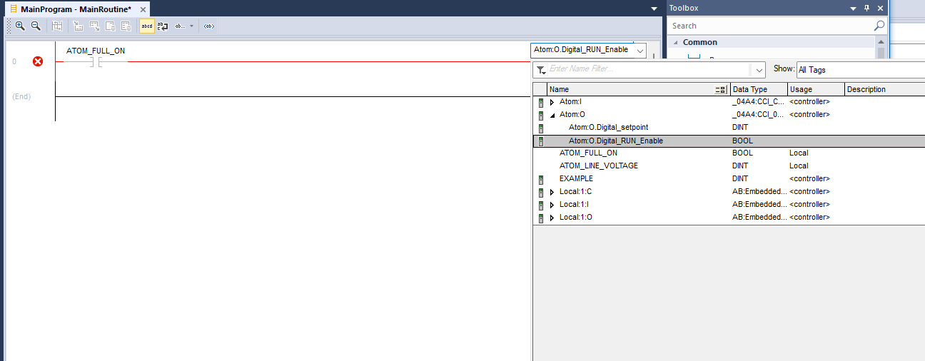
- Add an
Output Energizeinstruction and selectAtom:O.Digital_RUN_Enable:

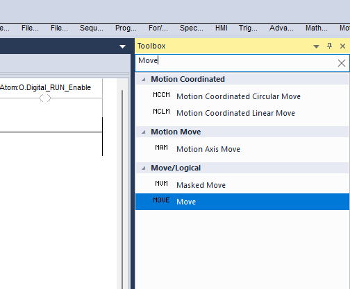
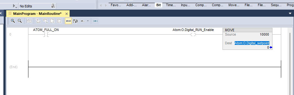
- Add a
Moveinstruction and set source to10000and dest toAtom:O.Digital_setpoint.
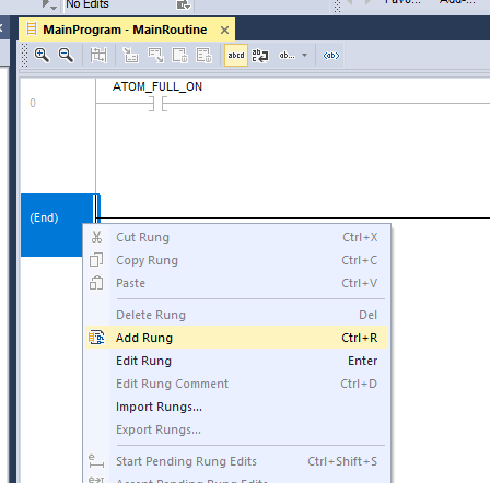
- Right-click and select Add rung. In this new rung, add a
MOVEinstruction and set source toAtom:I.AC_Line_Voltageand dest toATOM_LINE_VOLTAGE:
- Select the PLC dropdown and click Download to download the program to your PLC:
Ensure the switch on your PLC is set to
PROGmode before downloading.

- Flip the switch on your PLC to
RUNmode.
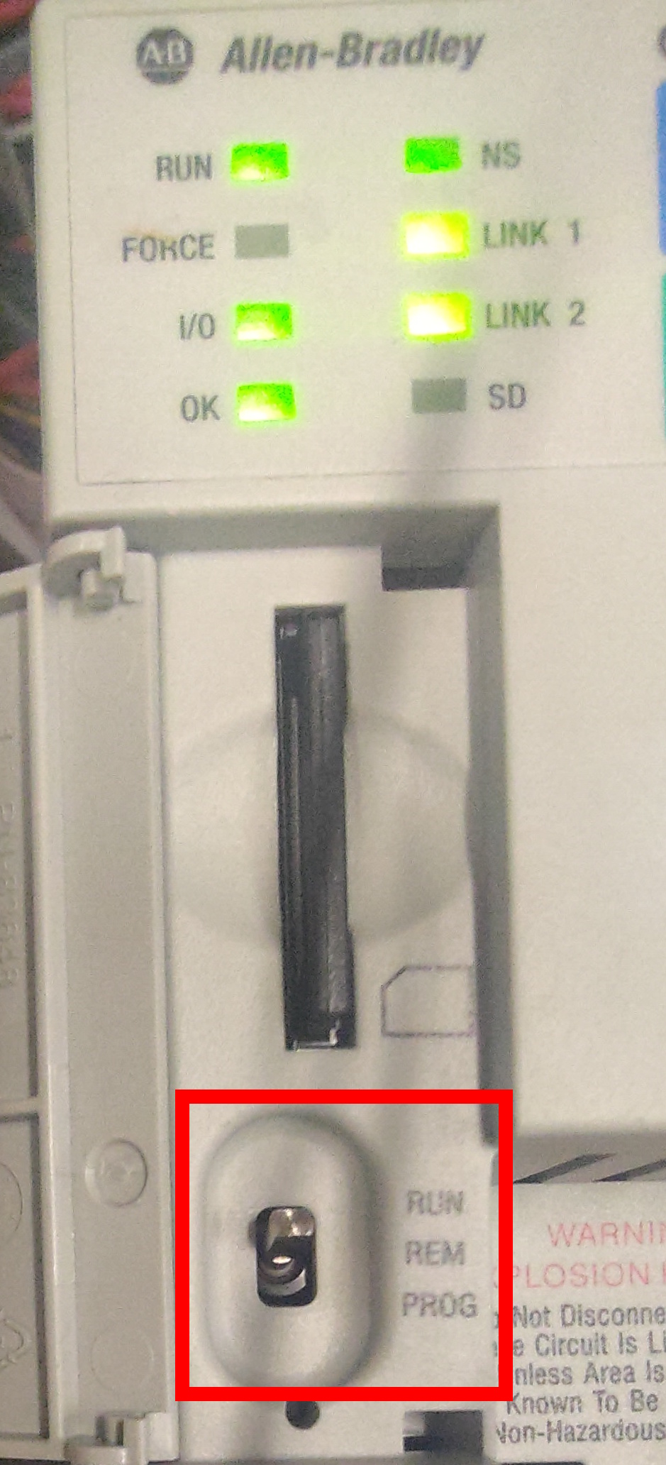
- If everything worked properly, the controller Run Mode indicator light should turn green:
Next, jump to the Creating a user interface section.
Structured Text
- Delete the default
MainRoutine:

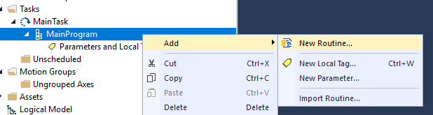
- Right-click
MainProgramand select Add Routine. Name itMainRoutine, set the Type toStructured Text, and click OK:

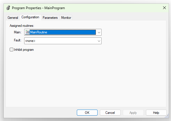
- Right-click
MainRoutine, select Properties, and ensureMainRoutineis set as the Main Routine in the Configuration tab:

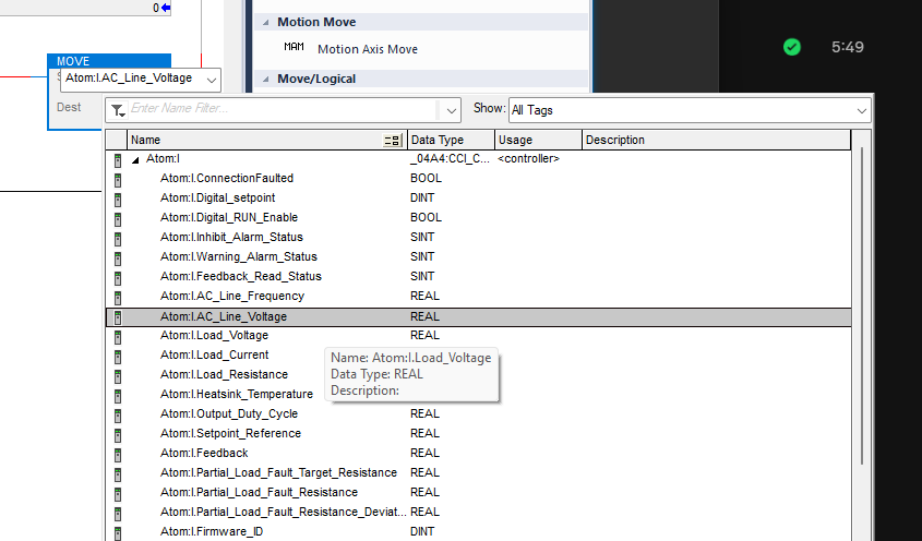
- Insert tags by right-clicking in
MainRoutineand selecting Browse Tags.

- You can insert
Atom:I(input) andAtom:O(output) tags to control ATOM:

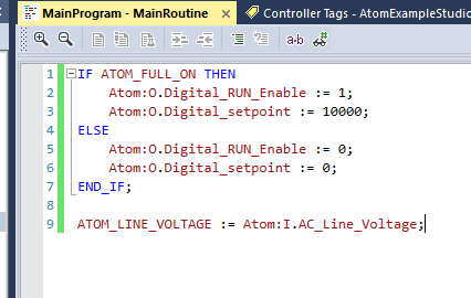
- Add the following code to
MainRoutine:
IF ATOM_FULL_ON THEN
	Atom:O.Digital_RUN_Enable := 1;
	Atom:O.Digital_setpoint := 10000;
ELSE
	Atom:O.Digital_RUN_Enable := 0;
	Atom:O.Digital_setpoint := 0;
END_IF;

ATOM_LINE_VOLTAGE := Atom:I.AC_Line_Voltage;
Next, jump to the Creating a user interface section.
Creating a user interface
Studio 5000 comes with a separate program called View Designer for creating user interfaces. It's usually installed at
C:\Program Files (x86)\Rockwell Software\Studio 5000\View Designer\ENU\V10\ViewDesigner.exe
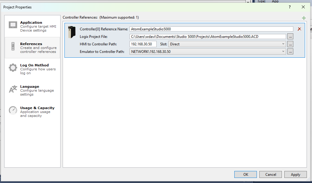
- Launch View Designer and create a new project with the following settings:
- Controller[0] Reference Name:
AtomExampleStudio5000 - Logix Project File:
path-to-your-project\AtomExampleStudio5000.ACD - HMI to Controller Path:
192.168.30.50 - Emulerator to Controller Path:
NETWORK\192.168.30.50
- Controller[0] Reference Name:
- Open
Screen_001:
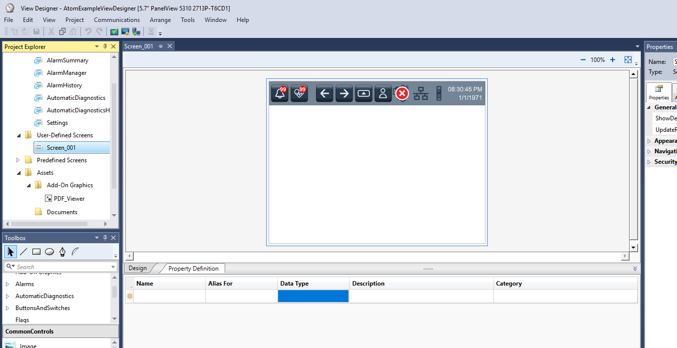
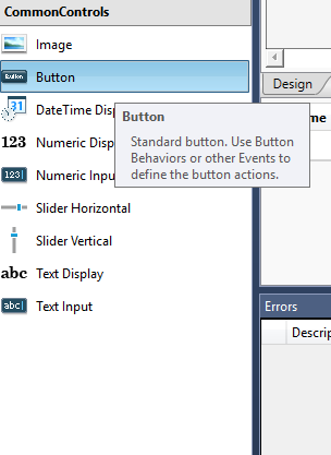
- In the CommonControls toolbox, drag three components onto the screen:
- Button
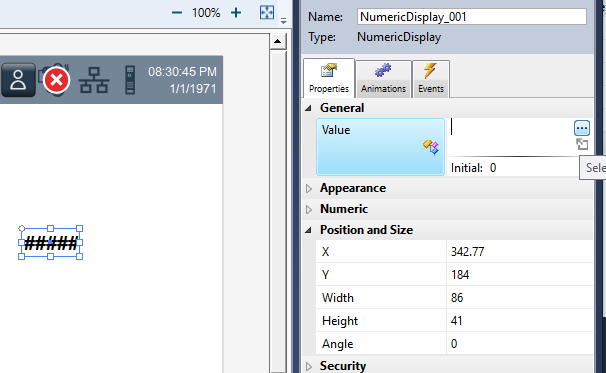
- Numeric Display
- Text Display
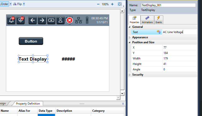
- Select the Text Display component and set the text to
AC Line Voltage:
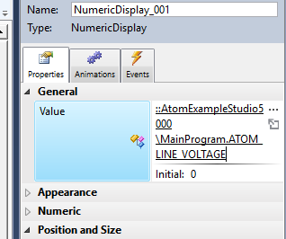
- Select the Numeric Display component and set the Value (in the Properties panel) to
ATOM_LINE_VOLTAGE:

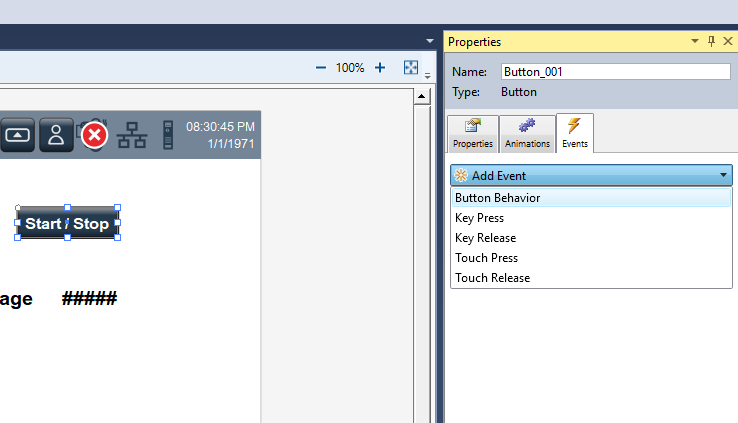
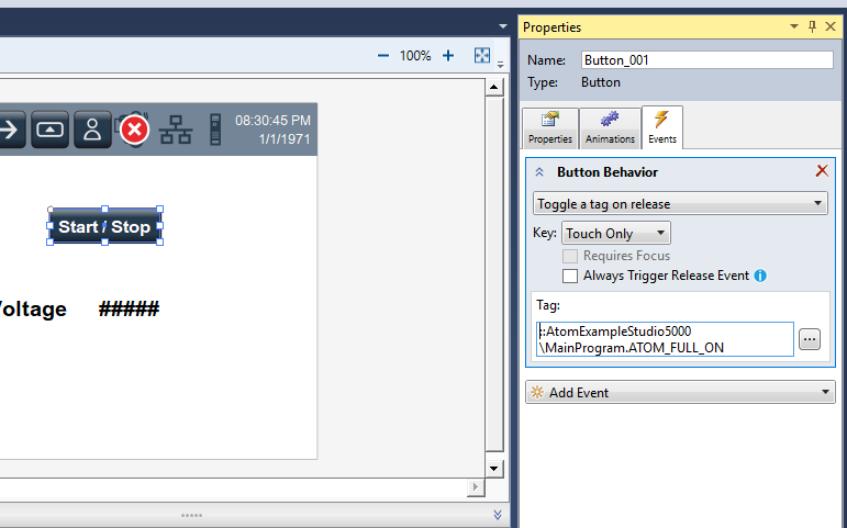
- Select the *Button component and set the text to
Start / Stop. In the Events panel, click Add Event, Button Behavior:
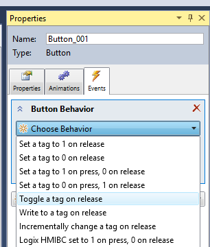
- Select Toggle a tag on release and set the tag to
ATOM_FULL_ON:

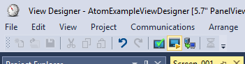
- Select the Emulate button to launch the HMI emulator:
-
Ensure your PLC is in
RUNif it is not already. -
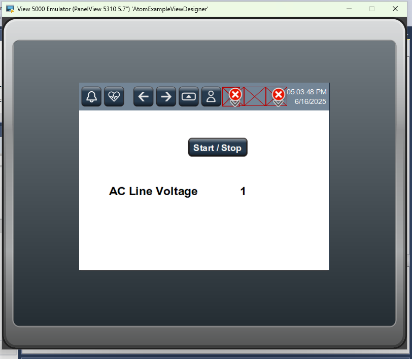
In the emulator, you can click
Start / Stopto toggle ATOM's operation. The AC Line Voltage display should show the current line voltage (in tenths of volts (e.g.,2300for230.0V)):
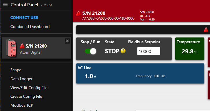
If you are connected to ATOM with Control Panel, you can watch the Stop / Run and Fieldbus setpoint controls change as you toggle the button in the Rockwell emulator.
Troubleshooting
Installation troubleshooting
Activation issues
If you use your PC for multiple PLC environments (like Siemens TIA, Codesys, etc.) you may run into activation issues caused by CodeMeter licenses.
Follow this guide to delete other CodeMeter licenses as Studio 5000 requires exclusive access to the CodeMeter license manager.
Your CodeMeter should look like this:

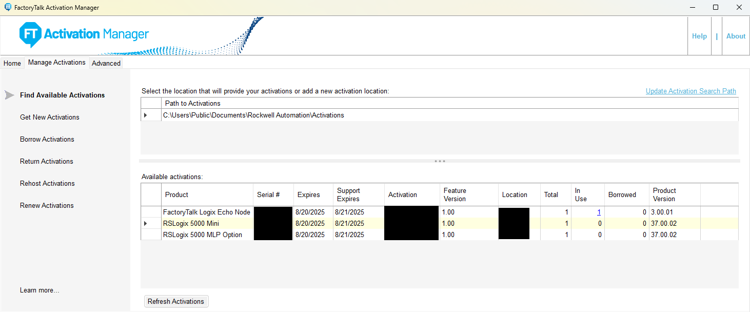
Factory Talk activation
Use Factory Talk Activation Manager to ensure your have a valid Studio 5000 license.
Can't connect to PLC or ATOM
Use the ping utility on Windows to check if your PC can reach the PLC/ATOM:
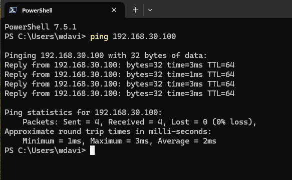
If:
- Ping is successful - you have a configuration problem with your PC
- Ping is unsuccessful - you have a hardware configuration, PLC configuration, or ATOM configuration problem.